Back To Basics — Networking — Dig deeper into IP Addresses
One of the most basic components of TCP/IP is IP addressing. Every device on a TCP/IP network must have a unique IP address.
Before you understand the details of how IP addressing works, you need ot understand how the binary numbering system works because binary is the basis of IP addressing.
Understanding Binary
Counting by ones
Binary is a counting system that uses only two numerals 0 and 1. In the decimal system we have 0–9, where the position of the digit has units, tens, hundred and so on. and represented as 10⁰, 10¹,10²…
In binary, you have only two numerals and the position in a binary number are called bits rather than digit represent the powers of 2 rather than powers of 10. 1,2,4,,16,32 and so on.
10111 = (1*2^4)+(0*2^3)+(1*2^2)+(1*2^1)+1*2^0) = 16 + 0 + 4 + 2+ 1 = 23
If you allocate 8 bits the largest value the number can store is 11111111 = 255 in decimal.
Logical Operations
Binary numbers are the logical way of handling special operations. Four basic logical operations : AND, OR, XOR , NOT
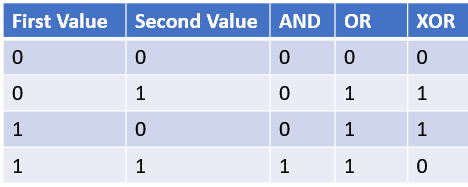
Logical operations are applied to binary numbers that have more than one binary digit by applying the operation one bit at a time.
IP Addresses
An IP address is a number that uniquely identifies every host on the IP network. IP addresses operate at the network layer of the TCP/IP protocol stack, so they are independent of lower-level data link layer MAC address such as Ethernet MAC addresses
IP addresses are 32-bit binary numbers which means a maximum of something in the neighborhood of 4 billion unique host address can exist throughout the internet. TCP/IP places certain restrictions on how IP addresses are allocated. This limits total number of suable IP addresses. New techniques are in place and a standard for 128-bit IP addresses has been adopted.
Network and Hosts
IP stands for Internet Protocol and its primary purpose is to enable communications between networks. As a result, 32-bit IP address actually consists of 2 parts
- Network ID( or network address): Identifies the network on which host computer can be found
- Host ID( or host address): Identifies a specific device on the network indicated by the network ID
Most of the complexity pf working with IP addresses has to do with figuring out which part of the complete 32-bit IP address is the network ID and which part is the host ID
Host ID cannot be all 0 which is reserved to recognize network itself. All 1 is used for broadcast request that is intended for all hosts on the network.
IP address representation
IP addresses are usually represented in a format known as dotted-decimal notation. In this notation, each group of eight bits an octet is represented by its decimal equivalent like 11000000 10101000 10001000 00011100 → 192.168.16.28
What about IPV6?
Most of the current internet is based on version 4 of the Internet protocol also known as IPv4. It has served internet well for more than 3 0years. The growth of internet has put lot of pressure on IPv4’s limited 32 bit address space. Eventually, though all the addresses will be assigned, and the IPV4 address space will be filled to capacity. When that happens, the internet will have to migrate to the next version of IP known as IPv6.
IPv6 is also called IP next generation or IPng. The most important feature is it uses 128 bits for internet addresses instead of 32 bits. the number of host addresses possible with 128 bits is a number so large.
340,282,366,920,938,463,463,374,607,431,768,211,456
If we have IPv6 addresses at the rate of 1 per millisecond and 1000 addresses every second — it would take 15 billion years to run out of the addresses.
Classification of IP addresses
Initially, the IP protocol was created the IP addressing scheme, they could have assigned an arbitrary number of IP address bits for the network ID and remaining as host ID. But there are networks where there are 1000’s of computers are connected. For some networks only 1000 are used and other 64000 IP addresses are wasted. As solution to this problem IP address divided in classes: A , B, C, D, E. A — C uses different size of network ID and host ID portion of the address. Class D is special type f address called multicast address. Class E is experimental address
First 4 bits of the IP address determines which class of IP address it is
Class A — The first bit is 0
Class B — The first bit is 1, second bit is 0
Class C — the first 2 bits are 1 and third bit is 0
Class D — The first 3 bits are all one and 4th is 0
Class E — First 4 bits are all 1
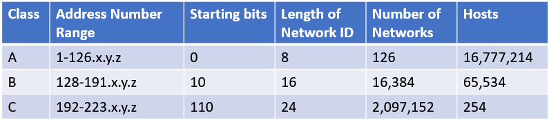
Class A addresses
Class A addresses are designed for very large networks. In a Class A address, the first octet of the address the network ID, and the remaining three octets are the host ID. Because only eight bits are allocated to the network ID and the first of these bits is used to indicate that the address is a class A address, only 126 class A networks can exists in the entire Internet. Each Class A network can accommodate more than 16 million hosts
Only about 40 Class A addresses are actually assigned to companies or organizations. The rest are either reserved for use by Internet Assigned Numbers Authority (IANA) or are assigned to organizations that manage IP assigned for geographic regions such as Europe, Asia and Latin America.
The special address 127.0.0.1 is called the loop-back address. A device at any IP address that sends a message to 127.0.0.1 is sending a message to itself. this may sound useless, but it plays important role in troubleshooting problems
Class B addresses
In a Class B address, the first two octets of the IP address are used as the network ID and the second two octets are used as the host ID. Because the first two bits of the first octet are required to be 10, in order to indicate that the address is Class B address. As a result, a total of 16,384 Class B networks can exits. All Class B addresses fall within the range 128.x.y.z to 191.x.y.z. Each class B address can accommodate more than 65000 hosts.
The problem with Class B networks is that even though they are much smaller than Class A networks, they still allocate far too many host IDs. Very few networks have tens of thousands of hosts.
Class C addresses
In a Class C address, the first three octets are used for the network ID and the fourth octet is used for the host ID. With only eight bits for the host ID, each Class C network can accommodate only 254 hosts. However, with 24 network ID bits, Class C addresses allow for more than 2 million networks.
The problem with Class C networks is that they are too small. Although few organizations needs the tens of thousands of host addresses provided by Class B address, many organizations needs more than few hundred. This led to the development called Subnetting.
Subnetting
Subnetting is the technique that lets network administrators use the 32 bits available in an IP address more efficiently by creating networks that are not limited to the scales provided by Class A,B and C IP addresses. With subnetting, you can create networks with more realistic host limits.
Subnetting provides a more flexible way to designate which portion of an IP address represent the network ID and which portion represent host ID. With standard IP address classes only three possible network ID sizes exist: 8 bits for Class A, 16 bits for Class B and 24 bits for Class C. Subnetting lets you select an arbitrary number of bits to use for network ID
- With this strategy, any network that needs more than 254 has to choose class B which has 64000 hosts and the IP addresses are wasted.
- Even if the organization has thousands of network devices, operating all those devices with the same network ID would slow the network to crawl. the way TCP/IP works dictates that all the computers with the same network ID must be on the same physical network. the physical network comprises a single broadcast domain. Which mean that single network medium must carry all the traffic for the network. For performance reasons, networks are usually segmented into broadcast domains even smaller than class C addresses provide
Subnets
A subnet is a network that falls within a class A,B,C network. Subnets are created by using one or more of the class A,B,or C host bits to extend the network ID. Thus, instead of the standard 8-, 16- , 24 bit network ID, subnets can have network IDs of any length.
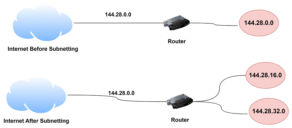
Here is an example of a network before and after subnetting has been applied. In the un subnetted network, the network has been assigned the Class B address 144.28.0.0. All devices on this network must share the same broadcast domain
In the second network, the first 4 bits of the host ID are used to divide the network into two small networks identified as subnets 16 and 32. To the outside world, it still appears as the single network. As a result, the packet sent to the device will be delivered to the router at 144.28.0.0. The router then considers the subnet portion of the host ID to decide whether to route the packet to subnet 16 or subnet 32
Subnet Masks
For subnetting to work, the router must be told which portion of the host ID should be used for the subnet network ID. this little sleight of hand is accomplished by using another 32 bit number known as subnet mask. Those IP address bits that represent the network ID are represented by a 1 in the mask and those bits that represent the host ID appear as a 0 in the mask. As a result, a subnet mask always has a consecutive string of ones on the left followed by a string of zeros.
In other words, the first 20 bits are ones, and the remaining 12 bits are zeros. thus the complete network ID is 20 bits in length and the actual host ID portion of the subnetted address is 12 bits in length.
To determine the network ID of the IP address, the router must have both the IPO address and the subnet mask. The router performs a bitwise operation called a logical AND on the IP address in order to extract netowkr ID. t operform a logial AND, each bit of the IP address is compared with the corresponding bit in the subnet mask. If the both bits are 1 he resulting bit in the network ID is set to 1. Thus , the network ID for this subnet is 144.28.16.0.
Network Prefix notation
Because subnet always begins with the consecutive sequence of ones to indicate which bits to use for the network ID, you can use shorthand notation — a network prefix — to indicate how many bits of an IP address represent the network ID. the network prefix is indicated with a slash immediately after the IP address followed by the number of network ID bits to use.
For Example, the IP address 144.28.16.17 with the subnet mask 255.255.240.0 can be represented as 144.28.16.17/20.
Network prefix notation is also called classless interdomain routing notation (CIDR) because it provides a way of indicating which portion of an address is the network ID and which is the host ID without relying on standard address classes
Default subnets
The default subnet masks are three subnet masks that correspond to the standard Class A, B and C address assignments.
Some additional details about subnet and subnet masks —
- the minimum number of network ID bits is eight
- The maximum number of network ID bits is 30
- Because the network ID portion of a subnet mask is always composed of consecutive bits set to 1, only eight values are possible for each octet of the subnet mask: 0, 128, 192, 224, 248,252,254 and 255
- A subnet address can’t be all zeros or all ones
IP block parties
A subnet can be thought of as a range or block of IP addresses that have common network ID. For example , CIDR 192.168.1.0/28 represents the following block of 14 IP addresses
192.168.1.1  192.168.1.2  192.168.1.3  192.168.1.4
192.168.1.5  192.168.1.6  192.168.1.7  192.168.1.8
192.168.1.9  192.168.1.10  192.168.1.11  192.168.1.12
192.168.1.13  192.168.1.14
Given an IP address in CIDR notation, it is useful to be able to determine the range of actual IP addresses that the CIDR represents. This matter is straightforward when the octet within which the network ID mask ends happens to be 0 as in this example. You just determine how many host IDs are allowed based on the size of the network ID and count them off.
However, what if the octet where the network ID mask ends is not 0? For example, what are the valid valid IP addresses for 192.168.1.100 when the subnet mask is 255.255.255.240? In this case, the calculation is a little harder. The first step is determine the actual network ID. You can do that by converting both the IP address and the subnet mask to binary and then extracting the network ID as in this example
IP address: 11000000 10101000 00000001 01100100 ( 192.168.100)
Subnet mask: 11111111 11111111 11111111 11110000
Network ID: 11000000 10101000 00000001 01100000 (192.168.1.96)
As a result, the network ID is 192.168.1.96
Next, determine the number of allowable hosts in the subnet based on the network prefix. You can calculate this by subtracting the last octet of the subnet mask from 254. In this case, the number of allowable hosts is 14
To determine the first IP address in the block, add 1 to the network ID. Thus, the first IP address in my example is 192.168.1.97. to determine the last IP address in the block, add the number of hosts to the network ID. In my example, the last IP address in 192.168.1.110. As a result, the 192.168.1.100 with subnet mask 255.255.255.240 designates the following block of IP addresses
192.168.1.97  192.168.1.98  192.168.1.99  192.168.1.100
192.168.1.101  192.168.1.102  192.168.1.103  192.168.1.104
192.168.1.105  192.168.1.106  192.168.1.107  192.168.1.108
192.168.1.109  192.168.1.110
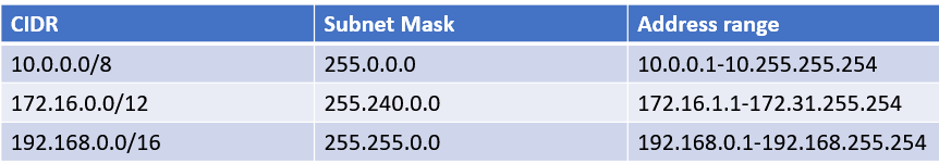
Private and public addresses
Any host with a direct connection to the internet must have a globally unique IP address. However, not all hosts are connected directly to the internet Some are on networks that are not connected to the internet. Some hosts are hidden behind firewalls, so their internet connection is indirect
Several block of IP addresses are set aside just for this purpose, for use on private networks that are not connected to the internet or to use on networks that are hidden behind the firewall. three such ranges of addresses exist, Whenever you create a private TCP/IP network, you should use IP addresses from one of these ranges.
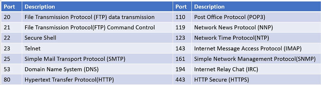
Pondering Ports
When you use an IP address, you often associate that IP address with a port, which enables a connection to a particular service. The best known port is port 80, which corresponds to the HTTP of the World wide Web. the combination of transport protocol, an IP address and a port is called an Internet Socket
Although IP addresses are defined at layer 3 of the OSI model, ports are a layer 4 construct. Layer 4 is the transport layer, so it makes sense that ports would live there.
Ports are commonly combined with IP addresses when used in URLs ( also known as web addresses.
Ports are represented by 32 bit number, so they range from 0 to 65535. there are three ranges of port numbers
- 0 to 1023 — These are called well known ports and they are used for the widely used services available on the internet.
- 1024 to 49151 — These are called registered ports, and they are assigned by the Internet’s governing authorities to various service providers.
- 49152 to 65535 — These are called dynamic ports, private ports or ephemeral ports. these ports cannot be registered and are used only for a specific communication.
Understanding Network Address Translation (NAT)
Nearly all firewalls use a technique called network address translation (NAT) to hide the actual IP address of a computer on the local network from the outside world. When that’s the case, the NAT device must use a globally unique IP address to represent the computer to the internet. Behind the firewall, though, the computer has private IP address. when packets cross the firewall, the NAT device translates the private IP address to the public IP address and vice versa
NAT is one of the foundational techniques that enables the internet to work. It is the way an organization can have dozens, hundreds, or thousands of computer on its network without requiring a separate public IP address for each computer. Instead, each organization has a relatively small number of public IP addresses that are assigned to the public-facing interfaces of its firewall. NAT enables all the computes behind the firewall to communicate with the internet.
What happens when an user sends a request to a local HTTP server?
An HTTP server that is on the same network as the user —
let us assume that the IP address of the local HTTP server is 192.168.0.100. and the IP address of the user’s computer is 192.168.0.50.
- The user’s computer sends and HTTP request in the form of an IP packet with the following address:
For the source, the transport protocol is TCP, the IP address is 192.168.0.50. The port number for the source is chosen by client and is typically high port number. Let us say 45444 for the source port.
For destination, the transport protocol is TCP, the IP address is 192.168.0.100 and the port is 80
2. The HTTP server receives the request, process it, and sends back and HTTP response in the form of an IP packer with the following address:
For the source, the transport protocol is TCP, the IP address is 192.168.0.100 and the port is 80
For destination, the transport protocol is TCP, the IP address is 192.168.0.50, and the port is 45444
This wont work if the user wants to send the request to and HTTP server in the internet because the IP address of the users computer is a private address and not a public address. So the HTTP server won’t be able to send a response to 192.168.0.50 because such an address doesn’t exist on the public internet.
This is the use case for NAT
The basic idea of NAT is that the firewall maintains an internal table of outgoing packet so it can remember which computer in local network has requested information from sites on the public Internet. Because more than one computer may make requests for information from the same Internet site, NAT exploits ephemeral ports to keep things straight
Let us assume that the firewall has following IP addresses:
- Outside IP address (public): 75.68.10.201
- Inside IP address(private) 192.168.0.1
Let also assume that the HTTP server is at 99.84.206.125 and a user whose private IP address is 192.168.0.50 uses a web browser to request information from the HTTP server. The HTTP request will have the following address information
- Source IP:192.168.0.50
- Source Port:45444
- Destination IP:99.84.206.125
- Destination Port : 80
Here is how it works:
- The firewall sees this packet and realizes that it must substitute its own IP address ( let us assume 192.168.0.1)
- The firewall selects a random port number from a pool of ephemeral port numbers which it will use to keep track of the request. For example, let’s say it picks port 42003
- The firewall records the following information in its NAT table for this request
- Source IP : 192.168.0.50
- Source Port:45444
- Destination IP:99.84.206.125
- Destination Port:80
- Temporary port:42003
4. The firewall modifies the packet by substituting its own public IP address for the source IP and the temporary port for the source port
5. The firewall sends the modified packet to the public internet
- Source IP: 75.68.10.201
- Source port:42003
- Destination IP: 99.84.206.125
- Destination port: 80
6. A few seconds later, the firewall receives an incoming HTTP response message with the following address information
- Source IP: 99.84.206.125
- Source port:80
- Destination IP:75.68.10.201
- Destination port:42003
7. The firewall peruses its NAT table and finds that this response matches the entry it recorded in Step 3
8. The firewall retrieves the original source IP address and port from the NAT table and substitutes it for the destination IP and port
The modified response message now has the following address information
- Source IP: 99.84.206.125
- Source port:80
- Destination IP: 192.168.0.50
- Destination port:45444
9. The firewall places the modified packet on the inside interface where the network can then deliver the packet to the original requestor( the user 192.168.0.50)
So what happens if two or more users have requests to the same web server at the same time? NAT is able to figure it out because each of those requests has a different temporary port number. For Example, the user in the preceding example got the port 42003. Another user might get 43859.
Happy Learning!!