Back to Basics — Networking — Routers : The post offices of Internet
A router is a device that works at Layer 3 of the OSI reference model which is Network Layer which is responsible for exchanging information between distinct networks. This is the functionality of router connecting tow or more networks so that packets can flow freely between them.
When the router receives a packet from one network that is destined from a device on another network, the router determines the best way to get the packet to its destination.
Routers are an indispensable part of any network. In fact, virtually all networks require at least one router.
Connecting to the Internet
A router is required for any network that needs access to the Internet. Such device is known as an Internet Gateway because it serves as a “gateway” to the internet.
Our Internet Service Provider(ISP) is one of the millions networks and your internet gateway connects to your private network of your ISP’s network. The ISP ‘s network in turn provides the routers that connect the ISP’s network to other networks which ultimately connects to the Internet backbone and the rest of he world.
A residential Gateway used at homes or small business have five distinct components —
- A router — used toe connect your private network to your ISP’s network
- A small switch, typically providing from three to eight ports to connect wired devices such as computers and printers
- A wireless access point (WAP) to connect wireless devices such as laptops or smart phones.
- A firewall to provide protection from intruders seeking to compromise your network
- A DHCP server to provide IP addresses for the computers and other devices on your network
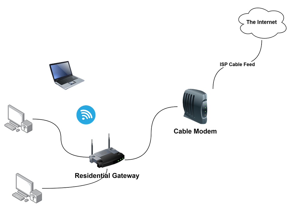
This above figure shows the set up at home. An ISP provides a cable feed into your house that connects to the cable modem, which provides a single Ethernet port to which you can connect a residential gateway. Computers on the home network are connected to the gateway’s switch ports and wireless devices connect via the Wi-Fi network. The gateway’s DHCP server hands out IP addresses to any devices connected to the network.
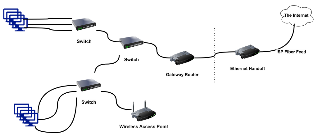
this figure shows the type of internet gateway typically used in large networks. Here the ISP delivers a high-speed fiber optic feed to the customer’s location and provides and Ethernet handoff, which is simply one or more Ethernet ports that the customer can connect to
The ethernet handoff establishes what is called demarcation point usually called simply the demark. the demark is simply dividing the line that establishes who is responsible for what. The ISP is responsible for everything between the Internet and demark, the customer is responsible for everything on the private network side of the demark.
A gateway router is used to connect the private network to the ethernet handoff. Much like a residential gateway, a gateway router typically provides several features into one combined device, including router, a small switch and a firewall. However, most business class gateway routers don’t provide Wi-Fi The wireless network is provided by dedicated WAPs. And the small switch provided by the gateway don’t serve the entire network, instead it is connected to a network of switches that in tun connect the network’s computers together.
The gateway router has small number of network interfaces. an external and internal interfaces are mandatory. the external interface labeled WAN on the device, connects to the ISP’s feed. the internal interface connects to private network.
Connecting Remote Locations
Routers also connect the geographically separated offices to form single network that spans multiple locations. You can do this by using a pair of gateway routers to create a secure virtual private network (VPN) between the two networks. Each network uses its gateway router to connect to the Internet and the routers establish a secure tunnel between themselves to exchange private information
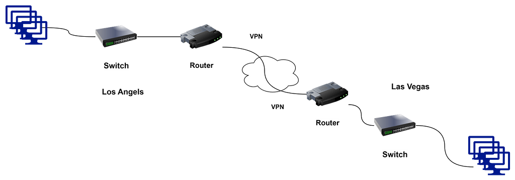
Figure shows how a VPN can be used to establish site-to-site tunnel between offices in Los Angels and Las Vegas. Each site has its own gateway router that connects to the Internet. The routers are configured to provide a VPN that securely connects the two networks.
Splitting up Large Networks
Large networks often have need for routers that are internal to the network itself. It divides the network into smaller, ore manageable networks all connected with routers.
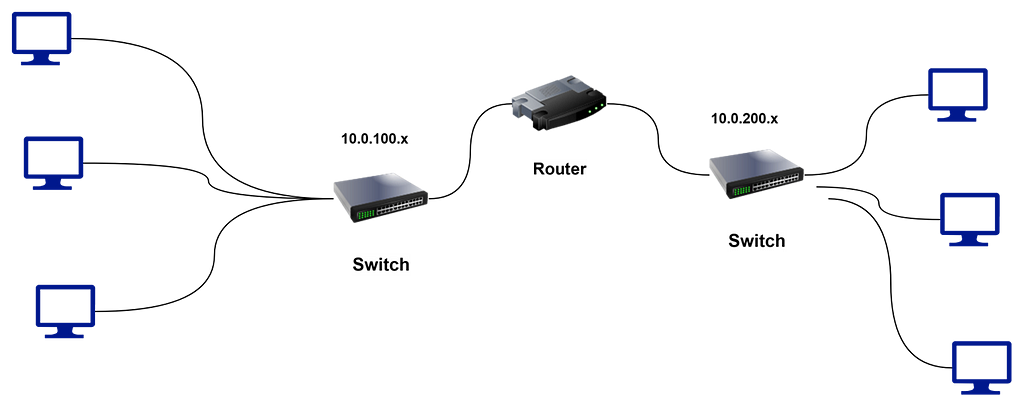
This is the simplified version of how it works. Large networks are segments into two smaller networks each on a different subnet; one on 10.0.100.x ( subnet mask 255.255.255.0)and other on 10.0.200.x ( subnet mask 255.255.255.0) . A router is used to provide the link between the two subnets, so packets can flow from one subnet to the other.
A router used in this way is called an internal router because it doesn’t connect a private network to a public network.
Separate internal routers are becoming less commonplace most switches now have routing functions inbuilt in to allow the subnets to communicate with one another.
Very large networks still required routers to handle the large amount of traffic that must flow between networks.
Understanding Routing Tables
Routers work by maintaining an internal list of networks that can be reached via each of the router’s interfaces. This list is called routing table. When a packet arrives on one of the router’s interfaces, the router examines the destination IP address of the incoming packet, consults the routing table to determine which of its interfaces it should forward the packet to and then forwards the packet to the correct interface.
The tick is building the routing table. For simple gateway router that connects a private network to the Internet, the routing table is created manually with static routes. Configuring the gateway router with static routes isn’t much complicated than configuring host computer iwth a static IP address.
For the complicated environments, where multiple routers are used on the private network, special routing protocols are used to build dynamic routes. these routing protocols are designed to discover the topology of the network by finding out which routers are present on the network and which networks each router can reach.
Let us assume that the private network for this business operates on a single subnet, and the IP address for the network is 10.0.1.0. with the subnet mask 255.255.255.0. The 6 computers in the private network has IP address 10.0.101.1 through 10.0.101.6 and the internal interface on the gateway will be configured with 10.0.1.254
Let us assume that the ISP provides you with the following information for your Ethernet handoff
- IP address: 205.186.181.97
- Subnet Mask: 255.255.255.255
- Default Gateway:107.0.65.31
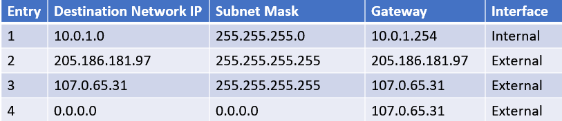
These are the entries in routing table
- Entry — Entry number
- Destination Network IP — This is the IP Address of the destination network. this column is used in conjunction with the subnet mask column to determine the network to which that packet’s destination IP address belongs
- Subnet Mask — The subnet mask that is applied to the destination IP address to determine the destination network
- Gateway — The address of the router that the packet should be forwarded to
- Interface — The interface that the packet should be forwarded through. Here, internal means the interface to which the internal private network is connected and external means the interface on which he ISP’s handoff is connected( In many gateways these are called LAN and WAN)
The four entries in the table are
- Entry 1 — Tells the router what to do with packets whose destination is on the internal network (10.0.1.x). The IP address of the internal network is 10.0.1.0 and the subnet mask is 255.255.255.0. these packets will be sent to the internal interface whose IP address is 10.0.1.254
- Entry 2 — This entry handles packets whose destination is the ISP’s gateway (107.0.65.31). the 255.255.255.255 subnet mask means the destination is a specific IP address not the network. these packets are forwarded to the ISP’s gateway on the external interface
- Entry 3 — This entry handles packets whose destination is the gateways' external interface which has been assigned the IP address 205.186.181.97 by the ISP. these packets are forwarded to the gateway address on the external interface.
- Entry 4 — This entry handles everything else. The network IP address 0.0.0.0 with no subnet mask means that all packets that aren’t caught by any of the other rules are forwarded our to the ISP’s gateway router 107.0.65.31 on the external interface.
The entries in the routing table are evaluated against each packet’s destiantion IP address to determine where the packet should be sent. The entries are evaluated in order, and the first one that matches is used to send the packet along its way.
For example, suppose a packet is received on the external interface and the destination address is 10.0.1.5. The router will first consider entry 1, applying the subet mask 255.255.255.0 to consider the 10.0.1.0. Because this matches the network ID in entry 1 the packet is forwarded to internal interface, where the switch can hand the packet off to the correct computer.
On the other hand, suppose a packet is received on the internal interface and the destiantion IP address is 108.211.23.42. When the router tries the first entry the subnet mask estracts the netwrok address 108.211.23.42. This does not match 10.0.1.0, so the router considers the second entry. The subnet mask 255.255.255.255 tells the eouter to compare the entire destiantion address with the IP address 107.0.65.31. Becaused the address does not match, the eoruter tries the third entry. Again, the subnet mask 255.255.255.255 tells the router to compare the entire destination address, this time with the IP address 205.186.181.97. Again, the addresses does not match, so the router moves to the fourth and final entry in the router table. The subnet mask is 0.0.0.0 reduces the entire destination to 0.0.0.0, which matches the destination network 0.0.0.0. therefore, the router forwards packet on to the ISP’s router at 107.0. 65.31 via the external interface.
In more complicated networks, there are a lot more than just four entries in the routing table. And in a busy network, router is likely handling hundred or even thousands of packets per second.
Happy Learning!!